The experimental campaig of the RIBES project had the objective of creating a database of measurements for the validation of FSI numerical analyses. Although several experimental static and dynamic public aeroelastic test cases are available (e.g. Agard 445.6, HiReNASD, EuRAM), the literature is relatively poor (at the date of the project start) concerning wind tunnel tests with realistic aeronautical wing structures. The RIBES experimental campaign was setup with the express objective to contribute in this direction.
The requirements for the wing tunnel measurements and for the model were:
- for the tests
- static pressure measurements under steady flow conditions;
- forces and moments measurements;
- model deformation measurements;
- stresses measurements on most significant structure locations;
- for the model
- scaled physical model of a metallic wing type of structure;
- rectangular shape and small thickness;
- installation of strain gauges and pressure pick-up points at its surface.
Test facility
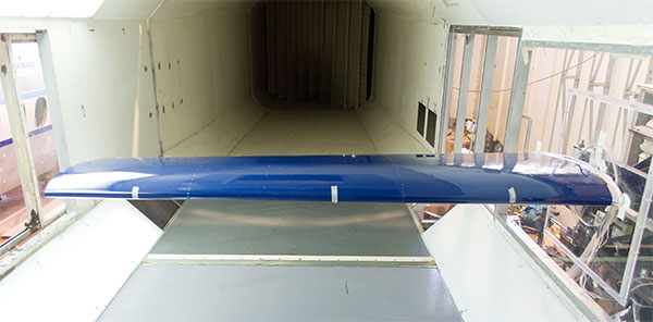
The tests were performed in the low-speed wind-tunnel of University of Naples “Federico II”. The facility is a close-circuit type with a test section dimension 2 x 1.4 meters. The maximum speed is about 45 m/s. The characteristics of the wind‐tunnel are:
- Type: closed circuit‐closed test section;
- Test section dimensions : 2.0 m x 1.4 m;
- Maximum speed : about 160 Km/h (45 m/s);
- Turbulence level : 0.1%;
- Temperature range : 10‐50 °C (during test the air temp increase);
- Speed range : 5‐45 m/s;
- Reynolds number : 1 ‐ 2 mil. for airfoil 2‐D tests (see below). Usually about 0.9 – 1.0 mil. For 3D model tests (chord of about 0.25 m);
- Dynamic Pressure : 15 – 1200 Pa;
- Stagnation pressure : Dyn press + ambient pressure (about 103500 Pa + q = 104700 Pa).
Wing model
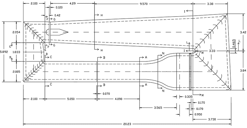
The model is installed on the side wall of the test section as a cantilever. It is a straight wing 1.6 meters wide, with a root chord of 600 millimetres and
0.7 as taper ratio. The wing box is a typical aeronautical structure with two C-shaped spars and ten ribs. The front spar is located at 20% of the chord and is maintained orthogonal to the symmetry plane. The rear spar is located at 65% of the chord. The reference surface is 0.816 m2, the Mean Aerodynamic Chord is 515 mm.
The final assembled model was measured by a HEXAGON metrology electronic harm in order to verify the correctness of the external shape. Some differences from the nominal geometry were observed mainly in the leading edge.
The model was instrumented with 81 pressure taps along 6 sections and twenty-five (16 uniaxial plus 3 rosettes with 3 signals) strain gauges located in several points of the structure.
Measurements configuration
The flow speed of the tests ranged between 30 and 40 m/s to which correspond Mach numbers approximatively from 0.1 to 0.12. Referring to a model MAC, the Reynolds number ranged between 1 and 1.4 millions. The displacement was measured detecting, by photogrammetry and laser scan, the position of a set of markers located on the wing surface. In order to correct themeasurements from the effect of deformation of the supporting system, the inclination of the balance wasmeasured during the test and used to restore the wing measured displacement to the value it would assume if rigidly constrained. Further refinements of correction were adopted detecting the deformation of the support by applying an inclinometer at the root structure of the wing. Transition trips has been applied at about 10 mm from the leading edge on both upper and lower surface in order to guarantee a fully turbulent boundary layer. The values of lift, drag, moment and preassure were measured at all test condition while the data on stress and displacement were reported for the most relevant conditions.
Numerical models
CAD model
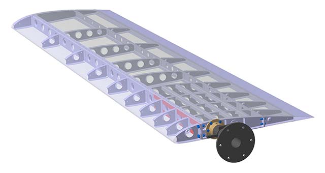
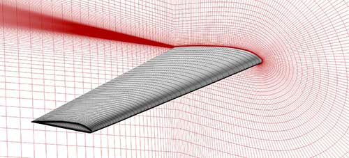
The geometry of the manufactured model was measured and reconstructed. A CAD model was generated from the cloud of points of eight measured sections from root to tip including the stations of the pressure taps lines. The procedure consisted in approximating the eight sets of measured points (one per section) by NURBS curves whose parameters (order, control points and knot vectors) were selected using an in-house developed optimization procedure in which the objective function was the minimization of the maximum distance between the curves and the input points. The curves maximum deviation from the measured geometry was contained within half millimetres. A sweep surface, interpolating the eight curves, was used to generate the wing skin. The internal structure topology was regenerated, in form of surfaces neglecting the elements thickness, starting from the CAD model of the nominal geometry and matching the external loft surface generated to approximate the measured wing geometry. With this procedure, a coherence between CFD, FEM model and real geometry should be guaranteed. The following figure shows the generated 3D CAD model. The blue translucent surfaces are used in the CFD model while the red entities refer to the internal reconstructed structure.
CFD model
The experimentally measured coefficients were corrected from the effects of wall blockage. The CFD numerical domain was then generated replicating the free-flight conditions. A multiblock H-C structured mesh topology, with hexahedral elements, was generated. The farfield is located 50 MAC in front, on the top, on the bottom and on the side of the model. The outlet surface is 60 MAC downstream the model. The grid is composed by 3.2 million of elements. The first layer of cells was set to ensure Y+ lower that one. The layers growth rate from the wall is in the order 1.2.
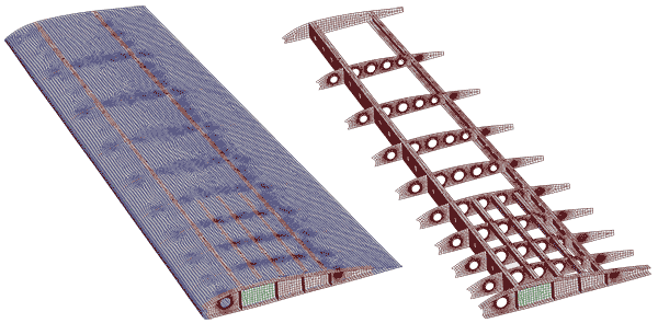
FEM model
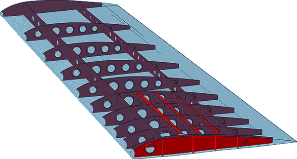
The FEM mesh is composed of 97000 shell elements distributed on surfaces extracted from the faces of ribs and spars and on
the reconstructed wing wet surface. The spar caps are joined to the skins linking the common nodes at the locations of the fasteners. The same procedure was adopted to join the stringers and the root rib to the skin. In the case of the front spar caps, the discrete junction involved the leading edge skin, the lower and upper panels (as on the real model). The other ribs caps were not modelled. Ribs and trailing edge skin are simply continuously constrained to the skin. The properties associated to the elements correspond to the thickness of the several wing elements. The wing is constrained at the central web in the root rib location where the real model is connected to the balance by the tubular rod.
Downloadable documents
- Tests documents
- Test article design (1.44 MB)
- Prototype manufacturing (10.2 MB)
- Experimental test report (12.8 MB)
- Numerical models
Related publications
Biancolini M. E., Cella U., Groth C., Chiappa A., Giorgetti F., Nicolosi F., “Progresses in FSI and Structural Optimization Numerical Tools within the EU CS RIBES Project”, EUROGEN 2017 International Conferences, Sep 13-15 2017, Madrid, Spain.
Ubaldo Cella, “Setup and Validation of High Fidelity Aeroelastic Analysis Methods Based on RBF Mesh Morphing”, Ph.D. thesis, University of Rome “Tor Vergata”, January 2017.
Biancolini M. E., Cella U., Groth C., Genta M., “Static Aeroelastic Analysis of an Aircraft Wind-Tunnel Model by Means of Modal RBF Mesh Updating”, ASCE’s Journal of Aerospace Engineering, Volume 29, Issue 6, November 2016, doi: 10.1061/(ASCE)AS.1943-5525.0000627.
Ubaldo Cella, Corrado Groth and Marco Evangelos Biancolini, “Geometric Parameterization Strategies for shape Optimization Using RBF Mesh Morphing”, in Advances on Mechanics, Design Engineering and Manufacturing, Lecture Notes series in Mechanical Engineering, pp 537 – 545, Sep. 2016, doi: 10.1007/978-3-319-45781-9_54.
Cella U., Biancolini M. E., Groth C., Chiappa A., Beltramme D., “Development and Validation of Numerical Tools for FSI Analysis and Structural Optimization: the EU RIBES Project status”, AIAS 44th National Congress, 2 – 5 September 2015, Messina, Italy.
Domiziano Beltramme, “Advanced Optimization of the WT Model of the RIBES Project”, M.Sc. Thesis, University of Rome “Tor Vergata”, February 2015.
Marco Fontanella, “Structural Design and Optimization of the Wind Tunnel model of the EU RIBES Project”, M.Sc. Thesis, University of Rome “Tor Vergata”, April 2014.